AI-translated from the Chinese original View original
As the hardware and software took shape, I wanted material to share on social media and video platforms. The project had already accumulated a set of 3D models. They provided an opportunity to try producing a polished presentation video and introduction images for the device.
This article walks through refining the models, synthesizing music, and creating animation with an agent. Here is the finished landscape-format video.
Modeling
The engineering models provided a useful starting point. I imported the two PCBs, enclosure, and fasteners from a STEP assembly into Blender, unified units and coordinates, and retained the relationships between parts. I could then compose shots of the complete device or isolate boards and enclosure parts for exploded views.

Models intended to verify dimensions and positions still needed another refinement pass for close-up shots. Surfaces, edges, and internal structures became much more apparent through the camera. I began with the tube interiors, then worked through PCB materials and other parts.
Refining the Nixie Tubes
The tubes were the focus of the device’s close-ups, and I wanted to reproduce their internal structure as closely as possible. The official datasheet offers limited dimensions, mainly the overall outline, character size, and pin positions. It provides too little information to reconstruct the electrodes, mesh, and supports directly.

Drawing source is page 3 of the iNixie Lab DGM01 datasheet.
I asked the agent to compare photographs of the actual tube and consult material on other tubes, including the IN-18, to understand the structure. My own observations supplied further corrections. The digits occupy different planes, so viewing angle changes how the electrodes, mesh, and supports occlude one another. The ten digit shapes, their depth order, and their mounting gradually approached the present result through repeated adjustments.
Some details have little impact at a distance but matter in close-up. The main vertical stroke of 1 is thicker than the other strokes, and 5 has distinctive bends and openings. A generic font struggled to reproduce that character. I eventually had the curves fitted to photographs, then refined the metal clips, insulating supports, mesh cage, and internal leads.
The glass needed separate attention. Alongside the cylindrical outline, I added inner and outer walls, a curved top, and the narrowed base so that its edges could reflect and refract light. At close range, those details and the internal metalwork together determine the tube’s sense of thickness.
The glow comes from excited gas around the electrodes and has a soft, mist-like appearance. I therefore asked the agent to model the metal electrodes and gas discharge separately. The metal stays non-emissive, while a separate volumetric emission layer around each character controls its glow.
Glow and glass highlights had to be judged together. Excessively bright reflections obscured digits and mesh. A very dark image lost the glass curvature. Soft lighting from the side and rear outlined the tube while keeping the orange-red digits prominent.

PCBs and Other Components
The board outlines and component positions were available already, but materials required several iterations. Plastic packages, metal leads, connectors, and the board surface each needed different reflectivity and roughness for convincing close-up detail.
The PCB surface also needed more than a flat black plane. Using the actual design files, I had the agent reproduce subtle relief from traces and copper areas, add silkscreen, and refine the surface appearance of the solder mask and copper regions. Changes in lighting and camera angle then made that relief visible.
The initial models lacked solder joints, making the components look as if they had simply been placed on the boards. I separated the pads and solder, added joint shapes around SMD leads and through-hole connections, and adjusted the silver-gray reflections. Joining the components visually to the board made the assembly much more convincing.

I refined other parts similarly, adding a matte grain to the enclosure, knurling and chamfers to the knob, and separate appearances for the LCD’s dark reflective surface and active display. Materials continued to evolve with the lighting in individual scenes.
Rhythm and Storyboarding
For pacing, I drew on a workflow shared by He Tongxue in a YouTube Short. Starting with a rough visual concept, I established the musical style and overall rhythm before refining shots and scenes. A video only a few seconds long has limited room, so duration, changes in pace, and transitions needed early decisions. As shots developed, I adjusted the music again.
-
Set the musical rhythm. Establish a beat and place accents for illumination, expansion, and reassembly.
-
Plan the shots. Allocate time between close-ups and wider views, choose cameras and movement, and refine the musical timing.
-
Preview with untextured models. Check pace, framing, and part motion.
-
Test-render key frames. Use final materials and lighting on representative frames to refine details.
-
Render the sequence. Export the full frame sequence and combine it with the soundtrack.
Synthesizing the Music
Before creating music, I had a rough set of shots in mind, including the glowing tubes, PCB close-ups, and an exploded assembly. I compared four soundtrack styles, chose one, and continued refining the shots around it.
The agent wrote scripts to generate audio waveforms directly. Sound can be represented as a waveform over time, and simple electronic timbres can be constructed programmatically. Frequency controls pitch, envelopes shape how a sound starts and fades, and noise, filters, and multiple voices can be combined into a rhythmic track.
I settled on a mechanical electronic style at 150 BPM. The script generated drums, bass, short plucked tones, and metallic percussion, then mixed them on a common timeline. As the animation developed, I adjusted their placement. A digit lighting up gets a short cue. The exploded view reduces rhythmic density. Reassembly builds momentum, with a brief pause before the final accent as the complete device lights up.
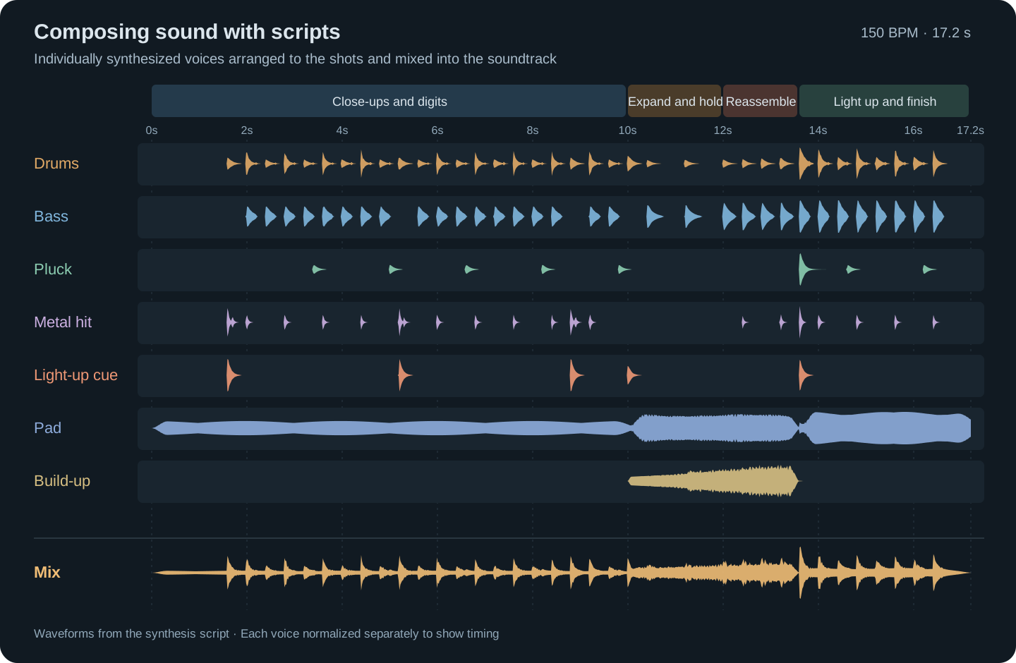
For a short piece with a clearly defined sound, scripted synthesis is inexpensive and highly controllable. Moving a cue to the instant a part settles or extending a background layer takes a change to timing and envelopes. Waveform generation, mixing, and export happen locally, allowing the soundtrack to evolve alongside the storyboard.
Designing the Shots
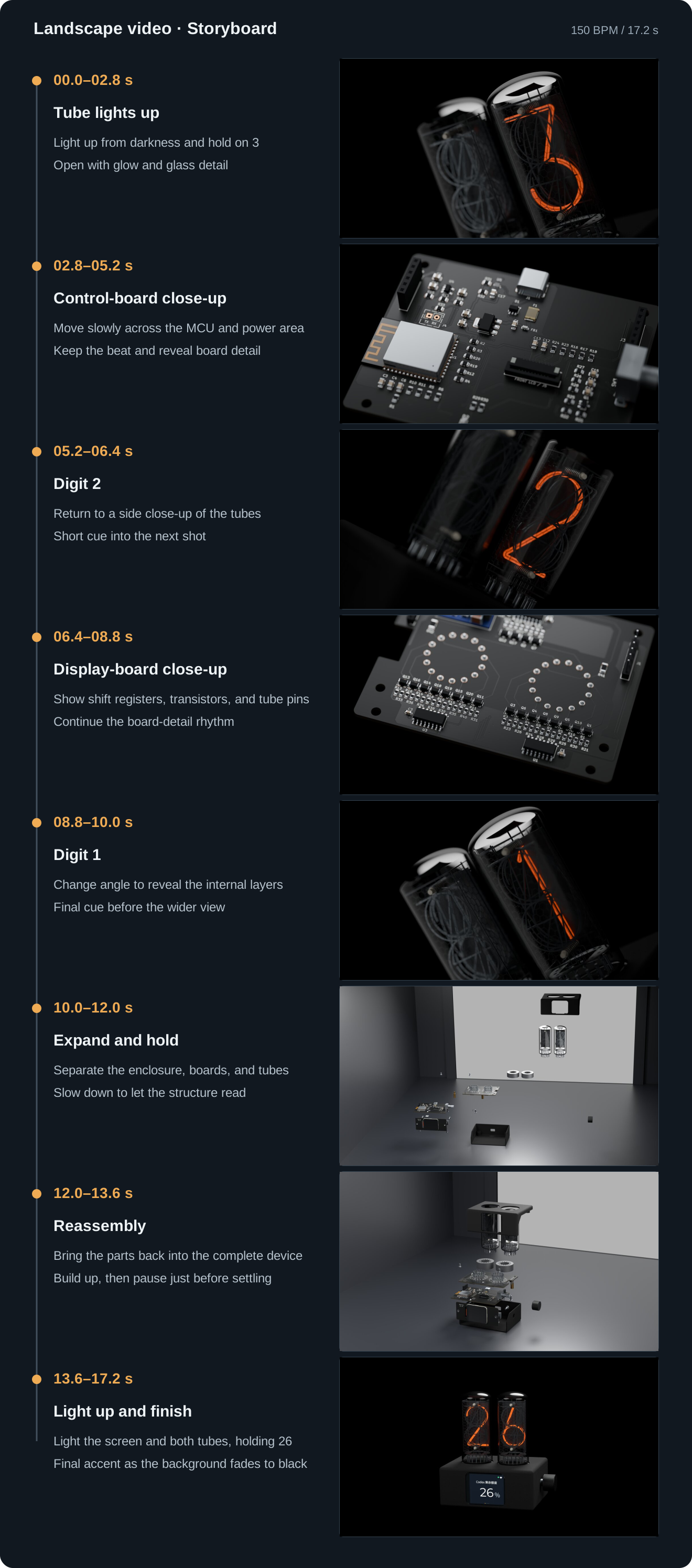
The storyboard turns the overall rhythm into individual shots, deciding cuts, slower movements, holds, and actions that coincide with musical accents. I then worked out the content of each scene.
-
Tube close-ups open with the internal layers, glass, and glow.
-
PCB close-ups move gently across components to show the two boards' details.
-
Expansion and reassembly reveal the enclosure and board structure, then return to a complete, illuminated device.
Landscape and portrait versions needed separate camera arrangements. A landscape exploded view can spread parts sideways, while a portrait composition needs more vertical layers. Close-ups also require repositioning the subject because cropping can remove the very detail the shot is meant to show.
Scene Design
The Exploded Assembly
An exploded view reveals structure normally hidden by the enclosure. Shells, boards, the front screen, and fasteners need enough separation to be readable while retaining a clear relationship to their assembled positions. I kept the complete assembly as the starting point and chose expansion directions and distances around the camera.
A spacious static layout still needs a feasible animation path. The upper shell’s two tube openings require it to rise along the tube axes before moving sideways. Screws behind the front board need to travel along their mounting directions, with timing offset slightly from the board’s return. Reflections and shadows can obscure those relationships in a final render, making an untextured preview easier to inspect.
I used those previews to check for obvious intersections, whether the upper shell stayed in frame, and whether each part remained legible at full expansion. Once the motion worked, I restored the finished materials. The sequence expands continuously, pauses briefly, and reassembles, giving the viewer time to understand the structure.

The Complete Device and Lighting
The closing shot returns to the complete device. Both tubes, the front screen, and the right-hand knob need to be visible, and the black enclosure needs separation from its surroundings. I wanted a dark image in which outlines and surface changes describe the form, with the brightest areas reserved for the glowing digits and screen.
The enclosure uses the matte grain of black PA12S, and the knob has knurling and beveled edges. The screen retains a reflective black surface while off and shows the quota interface when the assembled device lights up. Those material differences give the lights distinct surfaces to reveal.
Lighting changes with expansion and reassembly. At full expansion, the foreground lights reach their set brightness so the interior is visible. Background lightboxes then fade, followed by the wall and floor during reassembly, leaving the finished device against black. Local tube lighting follows the tubes as they move, keeping the glass within its illumination.
The black device needs a clear outline while the glow retains its color. Increasing the brightness of the entire scene makes glass and metal compete for attention. I focused on where light fell and whether reassembly, illumination, and the fading background formed a coherent sequence.

Rendering and Output
Before final rendering, I checked timing and motion with an untextured animation. Comparing several frames from expansion, the hold, and reassembly made it easier to see whether the shell cleared the tubes, parts stayed in frame, and the return sequence worked.

Next came key-frame test renders. I selected representative frames from each scene and rendered them with the intended lighting and materials. Glass reflections, glow color, PCB details, and dark enclosure surfaces all needed inspection. A material can look different as the camera or lights move, so I adjusted it against multiple frames before committing to the complete sequence.
Close-ups emphasize glass and metal, while exploded and whole-device shots must handle more surfaces and darker regions. I used scene-specific sampling and denoising, rendered full frame sequences locally on the GPU with Cycles, and combined them with the music.
Color handling also mattered. Exposure and display transforms influence the saturation of the orange-red glow. The rendered PNGs had already undergone display mapping, so the editing project needed consistent handling to avoid applying another display transform and changing color or contrast.

I also used the scenes to produce introduction images for platforms such as Xiaohongshu. Reframing the whole device, selected details, and internal structure for image layouts, with short explanations, provided another way to browse and share the project.
Reflections
What stood out was how smoothly AI participated across the process, and GPT’s current spatial understanding. Refining tube interiors, arranging expansion paths, moving cameras, and positioning lights could all progress through descriptions, previews, and further adjustments.
My role centered on creative direction and visual judgment. The character of the image, details worth emphasizing, shot duration, and balance between reflections and glow all needed decisions. The agent quickly turned those requirements into results I could watch and revise. Repeated comparison and selection brought the image closer to what I had in mind.
Last modified on 2026-11-07